Procedural world generation
- Edited

xyz I think the issue I'm having is that I'm generating the plane mesh in chunks, each beginning at the default position in world space, using that position in get_noise_3d(), committing to mesh, then translating the meshes to be in the correct position in terms of the map, but the noise function was sampled in the same location for each one. I will continue to work towards solving that issue, but I don't know if I am correct or not in my thinking.
- Edited
Lousifr Then it's just a matter of translating and scaling the uv coordinate you pass to projection function, So instead of always using full 0-1 range for the u coordinate for a chunk, scale/translate it to only part of that range. That way, the chunks will tile around the cylinder and then wrap after wanted number of chunks. If you for example want to have 4 tiled chunks, the first chunk would use 0-.25 u range, the second one would use .25-.5 and so on.
xyz How would I get it to use specific ranges for the u value? I've tried multiplying the scale in the x axis by 0.25, then adding to uv_translate using v, but to no avail.
for v in md.get_vertex_count():
var cyl_coord = cylinder_uv_to_xyz(md.get_vertex_uv(v) * (uv_scale) + (uv_translate))
md.set_vertex(v, md.get_vertex(v) + Vector3(0.0, noise.get_noise_3dv(cyl_coord) * elevation_scale, 0.0))- Edited
Lousifr Cylinder's surface covers full 0-1 UV space. So if you want to tile N chunks around the cylinder circumference (in U direction), each chunk's U range needs to cover 1.0/N of total U range. For 4 chunks that's 0.25.
To properly position chunks, every successive chunk needs to be translated in U direction for additional 1.0/N (i.e. the U width of a chunk). So for the chunk number I, the total U translation should be I*(1.0/N).
V translation is irrelevant for proper positioning. You might want to tweak V scale though, simply to match the UV ratio of chunk's sampling range to its physical XZ ratio, so that sampled noise frequency appears same in both directions. The more chunks you tile around the cylinder, the more you'll need to scale the V coordinate to compensate for the narrowing of the U range per single chunk.

- Edited
xyz So if I wanted to have a multiplier for the ground elevation that gets larger or smaller based on how high the ground is so as to allow for smooth transitions between sea level, level terrain (where the player will have its units), and mountains, should I use linear interpolation? Also, say I wanted to use a different noise function for generating mountains, how would I interpolate between the two based on the height of the mountain noise function? Or is this a better application for curves?
Just pointers on where I could learn more is enough.
- Edited
Lousifr Well you can do whatever you wish with noises, For example, sample two different noises and use a third noise as an interpolation or mask parameter, or remap/ramp/threshold noise in any way. It boils down to getting creative and experiment with simple math to achieve wanted results. Don't know it there are tutorial specifically for that. Maybe take a look at this article to get some ideas. There is also this presentation that breaks down terrain generation techniques in Minecraft which may also give you some insights on how to manipulate noises into getting what you want.

It's conceptually no different from having multiple different noise filled layers in something like photoshop to blend between.
Megalomaniak It's conceptually no different from having multiple different noise filled layers in something like photoshop to blend between
Yeah and things like Levels, Curves or Gradient maps, which are, mathematically speaking, just various remapping functions.
- Edited
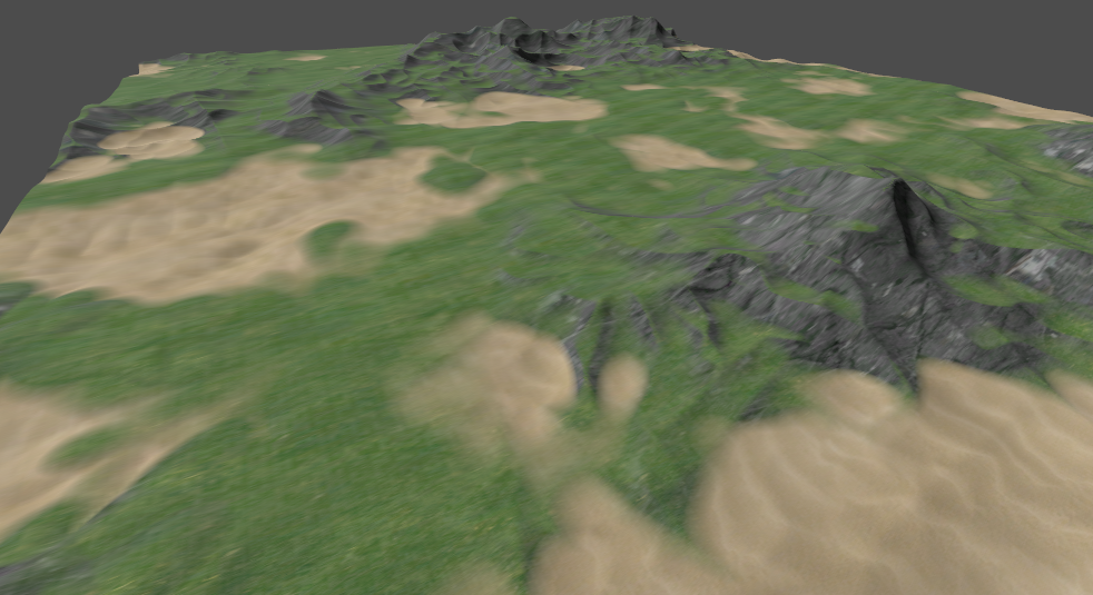
I've got the map looking almost how I want it before I move onto the next step, to be returned to later. I'm curious how I can get the elevation in the ocean regions to follow a curve that lowers the terrain more the lower the elevation value. How do I use curves to do this, or is there a better way?
var cyl_coord = cylinder_uv_to_xyz(md.get_vertex_uv(v) * uv_scale * Vector2(1.0 / num_chunks, 1.0) + Vector2(i * (1.0 / num_chunks), 0.0))
var plains = plain_noise.get_noise_3dv(cyl_coord) * (plain_scale)
var mountains = mountain_noise.get_noise_3dv(cyl_coord) * (mountain_scale)
var elevation = plains + (mountains - plains) * (mountains * 0.7)
md.set_vertex(v, md.get_vertex(v) + Vector3(0.0, elevation, 0.0))