• Godot Help
  • Particle shader - rotation on global axis instead of local axis?

I'm wondering how I can do a rotation on a global axis rather than the particle's local axis in a particle shader.

Here are my rotate y and x functions:

mat4 rotate_y(float theta) {
	return mat4(vec4(cos(theta), 0, -sin(theta), 0), vec4(0, 1, 0, 0), vec4(sin(theta), 0, cos(theta), 0), vec4(0, 0, 0, 1));
}

mat4 rotate_x(float theta) {
	return mat4(vec4(1, 0, 0, 0), vec4(0, cos(theta), sin(theta), 0), vec4(0, -sin(theta), cos(theta), 0), vec4(0, 0, 0, 1));
}

But these rotate along the local axis.

If I do this:

void start() {
	TRANSFORM *= rotate_y(PI/2.0);
	TRANSFORM *= rotate_x(PI/2.0);
}

I get something different than if I do the reverse:

void start() {
	TRANSFORM *= rotate_x(PI/2.0);
	TRANSFORM *= rotate_y(PI/2.0);
}

This is because the first rotation changes the local axis direction, and the second rotation then uses that new axis. How can instead do a rotation around the global x and y (and z) axis?

I'm very new to particle shaders and everything 3d. Let me know if there is an easier or better way to do anything. Thank you!

  • xyz replied to this.
  • Ok, yes I now realize I can do it like that. But I don't think it's possible to do it like that if I want to rotate the mesh around the y axis as well

    This is what I came up with:

    mat4 transform(vec2 origin, vec2 wind, float theta) {
    	vec4 y = vec4(sin(wind.y), 0, sin(wind.x), 0);
    	y.y = 1.0 - sqrt(pow(y.x, 2.0) + pow(y.z, 2.0));
    	
    	vec4 x = vec4(cos(theta), 0, -sin(theta), 0);
    	vec4 z = vec4(sin(theta), 0, cos(theta), 0);
    	
    	return mat4(x, y, z, vec4(origin.x + y.x / 2.0, y.y / 2.0, origin.y + y.z / 2.0, 1.0));
    }

    It looks like this works!

    origin is where the origin of the blade of grass is (where it comes out of the ground), wind is the strength of the wind in the x and z directions, and theta is how the blade of grass is the orientation of the blade of grass

    Makazau Don't rotate separately at all if you can. Euler rotation angles are problematic for multiple reasons anyways. Instead, determine the facing (forward) vector, calculate other two ortho-basis vectors using cross products and assign the basis vector components directly to the matrix. You'll get a single rotation matrix that orients the particle according to the basis.

      xyz Thanks for the response! Would you be able to give an example of the math? I unfortunately don't really understand what you mean. My linear algebra is pretty shaky 😬 .

      Or is there a good resource? I have found several that explain each individual rotation matrix, but none that has a good explanation of what you're talking about (probably due to my lack of knowledge)

      • xyz replied to this.

        Makazau How exactly you want your particles to behave? What determines their orientation?

          xyz For each particle say I want to have a mesh that is a straight blade of grass with length 1. I know the position I want the blade of grass to start at (a, b, c) and end at (x, y, z).

          What do I want to set the transform matrix to?

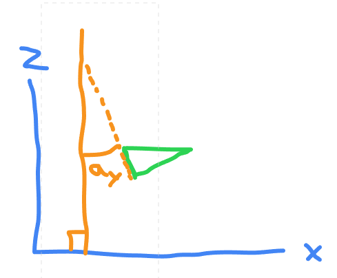
            Makazau Or, alternatively, I know abc as before but instead of knowing xyz I know az, the angle from the global x axis to the projection of the mesh on the xy plane and ax, the angle from the global z axis to the projection of the mesh on the yz plane

            Either would work for me

              Makazau Additionally, I also know the angle ay, which is the angle from the global z axis to the projection of the mesh on the xz plane. This part is less important

                Makazau Ok I think I've had a revelation. I shall try out an idea and report back soon

                • xyz replied to this.

                  Makazau For this you can actually get away with how you were doing it in the initial post. You have two angles: orientation, and inclination. First rotate around y axis by the orientation angle, and then around x axis by the inclination angle.

                  Ok, yes I now realize I can do it like that. But I don't think it's possible to do it like that if I want to rotate the mesh around the y axis as well

                  This is what I came up with:

                  mat4 transform(vec2 origin, vec2 wind, float theta) {
                  	vec4 y = vec4(sin(wind.y), 0, sin(wind.x), 0);
                  	y.y = 1.0 - sqrt(pow(y.x, 2.0) + pow(y.z, 2.0));
                  	
                  	vec4 x = vec4(cos(theta), 0, -sin(theta), 0);
                  	vec4 z = vec4(sin(theta), 0, cos(theta), 0);
                  	
                  	return mat4(x, y, z, vec4(origin.x + y.x / 2.0, y.y / 2.0, origin.y + y.z / 2.0, 1.0));
                  }

                  It looks like this works!

                  origin is where the origin of the blade of grass is (where it comes out of the ground), wind is the strength of the wind in the x and z directions, and theta is how the blade of grass is the orientation of the blade of grass

                    Makazau Also, this keeps the x and z basis vectors flat so the blade of grass is always flat where it comes out of the ground

                    Thanks @xyz for all the help. You really helped me understand basis vectors!

                    Makazau But I don't think it's possible to do it like that if I want to rotate the mesh around the y axis as well

                    Of course it's possible. I thought you'll rotate around y (for orientation) and then around x (for inclination). You can rotate around all 3 axes just need to take care of the order depending on what type of control you need over the blade orientation.