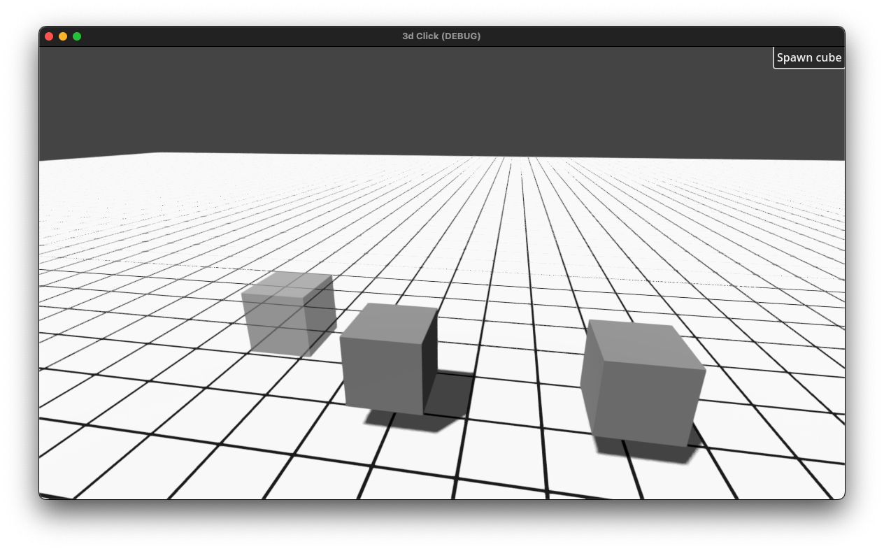
My cube mover project is coming along and I can move and shuffle them around by offsets of 1 as seen below:

Now I want to support the user by putting a grid overlay on the floor so they have a visual clue how the cubes are snapping. What would be the best approach to achieve that?

Max

  • xyz replied to this.
  • max_godot Hm, you should set the plane size to 1,1 and adjust its size by scaling it. But here's more bulletproof shader version that handles both, scaling and mesh sizing:

    shader_type spatial;
    render_mode blend_mix, unshaded;
    
    uniform float gridlineOnEvery = 1.0;
    uniform float lineThickness = .01;
    uniform vec2 originOffset = vec2(0.0, 0.0);
    uniform vec4 color: source_color = vec4(0.0, 0.0, 0.0, .5);
    
    varying vec2 pointWorld;
    
    void vertex(){
    	pointWorld = (MODEL_MATRIX * vec4(VERTEX, 1.0) ).xz - originOffset;
    }
    
    void fragment() {
    	float thick = lineThickness / gridlineOnEvery;
    	vec2 df = fract(pointWorld / gridlineOnEvery + thick / 2.0);
    	float grid = step(thick, df.x) * step(thick, df.y);
    	ALBEDO = color.rgb;
    	ALPHA = (1.0 - grid) * color.a;
    }

    max_godot A shader, or a plain grid texture on the ground material.

    I made a visual shader for a grid just now since I was feeling out of practice on shaders and hadn't touched Godot's visual shaders yet.

    @max_godot Let me know if you want to see the graph & a short walk-through.

      award that would be awesome to have a starting point! I was browsing the Godot tutorial yesterday but this would be super helpful!


      On the left side, we are basically setting up the pattern to repeat. I'm using UVs here which for a simple quad go from 0 to 1, but you might prefer to use worldspace rather than UVs for your 3D geometry. Your math will have to change but the adjustments shouldn't be hard to figure out.

      The constant 25 represents our number of rows and columns. We multiply that by 2π because that is the period of the cosine function we'll use later. We multiply our UVs by that, and then separate out our X and Y because we're using them for vertical and horizontal lines respectively. Then we apply cosine to those values. This gives us a repeating "wave" between 0 and 1.

      But we don't want a wave, we want lines. That is what we use the step function for. Step is basically if x > edge: return 1; else: return 0 but optimized for shaders. I chose 0.9 as the edge. Changing that will change the line thickness.

      Now we have a number, 0 or 1, that tells us whether to draw a line or not. We use that to mix the colors for each direction, and then combine the directions together with a color operation. I used darken here, because the grid color is black, but other operations will work better for other inputs/results. The two color constants don't necessarily need to be colors. It might make sense for the first one to be a texture, or a whole nother bit of shader for lighting/etc.

      My output is color, because this is just a CanvasItem shader, but you would want to make a Spatial shader, and so your output would be albedo.

      Anyways, this shader probably won't work perfectly out of the box for you. You'll need to make adjustments for your situation if you want to use it and have it look right.

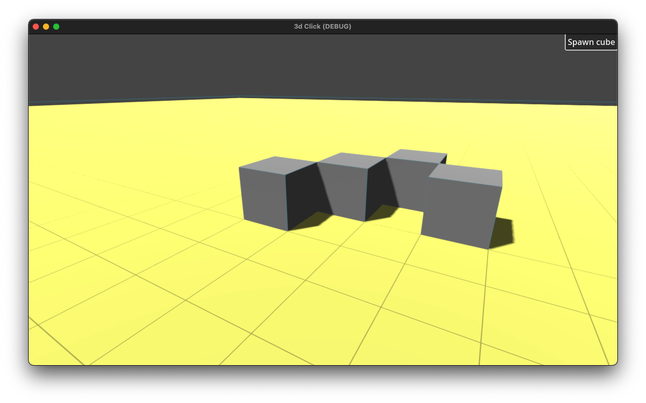
        award Thanks for the great tutorial! When I am applying the shader to my BoxMesh though it wraps it around the whole cube and not just the top surface. Is there a way that I can specify the shader per surface (screenshot below with a setting of 10)?

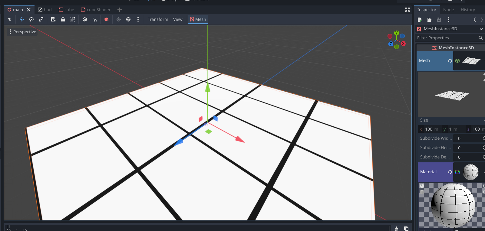
        I have also used PlaneMesh instead which looked way better but for somer reason my cubes are then floating above it. Also it looks like as if the grid is offset by a couple cm - is there a way for me to control that? Below example when using a PlaneMesh

        • xyz replied to this.

          max_godot You probably want a world space grid that is projected onto the horizontal plane. Here's the shader:

          shader_type spatial;
          render_mode blend_mix, unshaded;
          
          uniform float gridlineOnEvery = 1.0;
          uniform float lineThickness = .03;
          uniform vec2 originOffset = vec2(0.0, 0.0);
          uniform vec4 color: source_color = vec4(0.0, 0.0, 0.0, .5);
          
          void fragment() {
          	vec2 pointWorld = (MODEL_MATRIX * vec4(UV.x-.5, 0.0, UV.y-.5, 1.0) ).xz - originOffset;
          	float thick = lineThickness / gridlineOnEvery;
          	vec2 df  = fract(pointWorld / gridlineOnEvery + thick / 2.0);
          	float grid = step(thick, df.x) * step(thick, df.y);
          	ALBEDO = color.rgb;
          	ALPHA = (1.0 - grid) * color.a;
          }

          Make a shader material with it and put it as a second pass in your ground material. The grid will be blended over the original material.
          You can customize: grid step, line thickness, color/transparency and origin offset via shader params. Everything is in world space.

            Ah, this is good learning for me too. I didn't know about fract before. I was searching for modulo and couldn't find anything.

            max_godot, xyz's shader here is better in several ways so please give it a look.

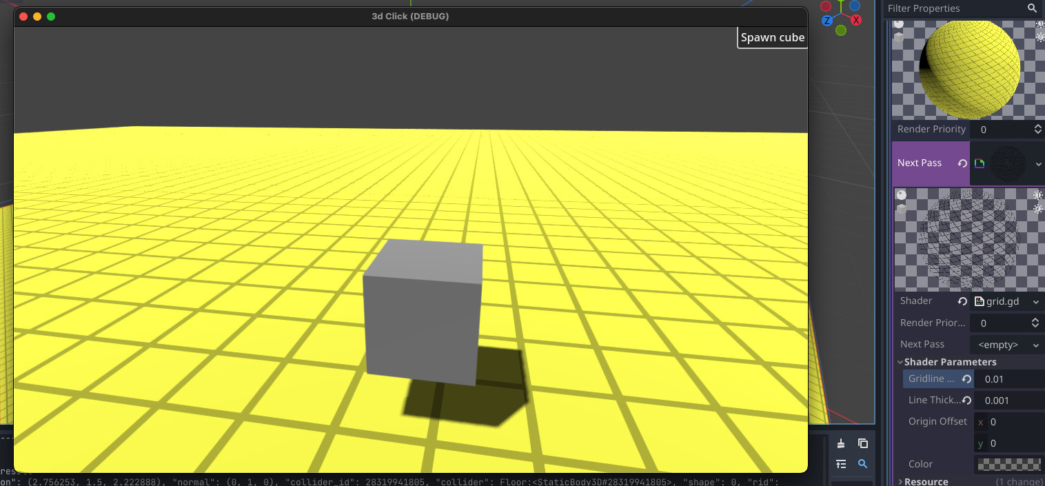
            xyz thanks for that! I have applied it and not sure if I got it right but I actually only get the grid to the proper sizes if I set the gridlineOnEvery parameter to 0.01

            and again I have the floating cube issues now if the mesh is a PlaneMesh and also there is an offset again. Changing it to BoxMesh also does not really help :/

            I have attached the project in case anyone wants to take a look:

            https://www.dropbox.com/scl/fi/3ulqe48og28dttam5gvif/3DClick2.zip?rlkey=i2pyoksv97ya7fs06st7b39kf&dl=0

            • xyz replied to this.

              max_godot "Floating" has noting to do with the shader. Adjust yor geometry as you see fit. The shader will project absolute world space grid onto any object in any position. gridlineOnEvery should match the size of your cube.

                max_godot Hm, you should set the plane size to 1,1 and adjust its size by scaling it. But here's more bulletproof shader version that handles both, scaling and mesh sizing:

                shader_type spatial;
                render_mode blend_mix, unshaded;
                
                uniform float gridlineOnEvery = 1.0;
                uniform float lineThickness = .01;
                uniform vec2 originOffset = vec2(0.0, 0.0);
                uniform vec4 color: source_color = vec4(0.0, 0.0, 0.0, .5);
                
                varying vec2 pointWorld;
                
                void vertex(){
                	pointWorld = (MODEL_MATRIX * vec4(VERTEX, 1.0) ).xz - originOffset;
                }
                
                void fragment() {
                	float thick = lineThickness / gridlineOnEvery;
                	vec2 df = fract(pointWorld / gridlineOnEvery + thick / 2.0);
                	float grid = step(thick, df.x) * step(thick, df.y);
                	ALBEDO = color.rgb;
                	ALPHA = (1.0 - grid) * color.a;
                }

                xyz ah, got the floating issue! That was my snapper vector with

                var snapper = Vector3(1,1,1)

                changing that to

                var snapper = Vector3(1,0,1)

                fixed the issue. 🙂

                • xyz replied to this.

                  @xyz @award finally got it, adjusting the offset by 0.5 for x and y made it perfect! 😃
                  Thank you so much for your help guys, I'll probably spend the weekend trying to understand what the shader is actually doing ... 🙂

                  max_godot Note that your cube's pivot is at its center, so its center will snap to whole units, not its corners.